3D Views
Three-dimensional image data, as well as regions of interest, multi-ROIs, meshes, graphs, and vector fields, can be viewed in the 3D view that is part of a scene. You should note that 3D views include an Axis Indicator, which displays the orientation of the current view, and also provides access to the Movie Maker panel, in which you can create animated sequences that tell compelling stories (see Movie Maker Interface). You should note that 3D views can be shown in perspective or orthographic projections.
3D scene view with multiple objects

The options in the 3D Scene's View Properties on the Main tab allow you to modify the properties of 3D views, while the options in the Data Properties and Settings Panel let you modify the appearance of datasets and other objects. See Using the Manipulate Tools for more information about tracking, panning, and zooming objects in 3D views. A right-click menu is also available to open the Movie Maker panel or to change the current view (see 3D View Pop-Up Menu).
Dragonfly offers the opportunity to view objects in both perspective and orthographic projection modes. In the familiar and default perspective mode, objects are subject to foreshortening and will appear smaller as their distance from the camera increases. In the parallel projection of orthographic mode, there is no foreshortening or vanishing point and dimensions can be communicated unambiguously.
Although perspective viewpoints can provide more information about depth and often tend to appear more realistic, orthographic viewpoints can make it much easier to compare objects, such as the parts of a molecule, as there is no question about how the viewpoint may affect the perception of distance or size. In addition, a scale bar is available for orthographic views (see Scale Bar for Orthographic Projections).
Perspective (on left) vs orthographic (on right) projections

While working, you can easily switch between orthographic and perspective modes to get a better sense of an object. Orthographic projection mode is selectable on the Scene’s Views Properties panel and in the pop-up menu for 3D views. You can also choose Orthographic as the default projection mode (see Selecting the 3D Settings Preferences).
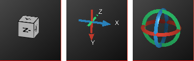
The Axis indicator, which can be shown as a cube or axes, displays the orientation of the current view.
Axis Indicator styles
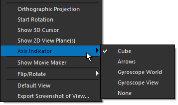
You can show or hide the Axis indicator, as well as choose its style, as follows:
- Right-click the required 3D view and then choose Axis Indicator in the pop-up menu.
- Choose Cube, Arrows, Gyroscope World , Gyroscope View, or None in the submenu, as required and as shown below.
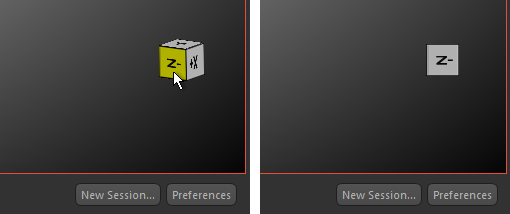
You can automatically align 3D views with the X, Y, or Z axis by double-clicking on the Axis indicator, as shown below.
Axis indicator
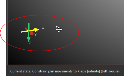
In some cases, you may want to constrain pan movements to a single axis. For example, when creating an animated sequence.
After changing the axis indicator to Arrows, you can then activate any of the directional arrows and then pan within a constrained direction, as shown below. You should note that when an axis is selected, it turns
yellow.
Pan movement constrained to X axis
The following configured actions and their default settings are available for constraining pan movements.
| Action | Description |
|---|---|
| Constrain Pan movements to X-axis (Infinite mode) | Left mouse |
| Constrain Pan movements to X-axis (Infinite mode) | Left mouse |
| Constrain Pan movements to X-axis (Infinite mode) | Left mouse |
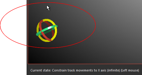
You can constrain Track movements to a selected axis, as shown below, when the Axis indicator is in Gyroscope World or Gyroscope View mode. You should note that when an axis is selected, it turns yellow.
Track movement constrained to rotation in the X axis
The following configured actions and their default settings are available for constraining track movements.
| Action | Description |
|---|---|
| Constrain Track movements to X-axis (Infinite mode) | Left mouse |
| Constrain Track movements to X-axis (Infinite mode) | Left mouse |
| Constrain Track movements to X-axis (Infinite mode) | Left mouse |
The text annotations show information about the current image in the 3D view, such as the window level values. These annotations are interactive and can be used to adjust the view, as described in the following table. See Selecting the Fonts Preferences for information about customizing the appearance of the text annotations.
| Description | |
|---|---|
|
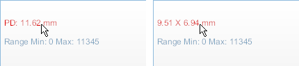
X by Y (size) or PD (distance to the camera's pivot point) |
Indicates the distance to the camera pivot point for perspective views, as shown below on the left, or the dimensions of the 3D view when you are in Orthographic view mode, as shown below on the right.
|
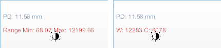
| Window Leveling |
Indicates the current window leveling applied to the selected image data. You can choose to display the window width (W) and window center value (C), as shown below on the left, or the minimum and maximum values of the selected range, as shown below on the right. These options are available as a preference (see Miscellaneous Preferences).
|
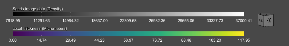
Legends are available for 3D views to show how values are mapped to the grayscale tones of image data and to the colors of scalar data. If required, you can re-position the legends by dragging them anywhere inside a view. You can also position a legend vertically or horizontally.
Legends
Do the following to change the orientation and/or size of a legend:
- Right-click the legend and then choose Vertical or Horizontal in the pop-up menu.
You can choose a default orientation for legends in the 2D Settings preferences (see Selecting the 2D Settings Preferences).
- Drag from the start or end point of a legend to change its width or height.
Two active view icons — Camera and View — are available for the current 3D view.
- The Camera
 icon lets you export multiple screenshots (see Exporting Screenshots From the Multiple Screenshots Panel) or copy a screenshot of the current view to the clipboard (see Copying Screenshots to the Clipboard).
 - The View
 icon lets you drag the display's GUID to the Python Console.
A floating scale bar is available for 3D views showing orthographic projections (see Perspective and Orthographic Projection Modes) to show the relative size of an object. If required, you can re-position the scale bar by dragging it anywhere inside the view.
The appearance and orientation of scale bars views can be customized through a contextual menu and set in the Annotations preferences (see Selecting the Annotations Preferences).
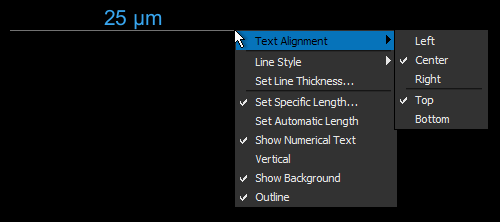
| Description | |
|---|---|
| Text Alignment | Lets you choose how text is aligned. Text can be aligned left, center, or right horizontally, as well as vertically on the top or bottom of the scale bar. |
| Line Style | Lets you choose a line style that has no hash marks, end hash marks, or half hash marks. |
| Set Specific Length | Lets you choose a specific length for the scale bar. |
| Set Automatic Length | Sets the length of the scale bar so that it automatically adjusts to the size of the view. |
| Show Numerical Text | If selected, shows the length of the scale bar. |
| Vertical | If selected, aligns the scale bar vertically. |
| Show Background | If selected, a semi-transparent background will be added to the scale bar. |
| Outline | If selected, an outline will be added to the background of the scale bar. |
A right-click or pop-up menu for 3D views provides access to the Movie Maker panel, macros, and to the different views available for the displayed data.
| Description | |
|---|---|
| XY | Changes the selected view to the XY axis representation (see 2D Views). |
| XZ | Changes the selected view to the XZ axis representation (see 2D Views). |
| YZ | Changes the selected view to the YZ axis representation (see 2D Views). |
| Image Plane | Changes the selected view to the image plane representation. This is the plane in which the data was acquired (see 2D Views). |
| Orthographic Projection | Toggles the projection mode of the 3D view between perspective and orthographic projection modes (see Perspective and Orthographic Projection Modes). |
| Start/Stop Rotation | Lets you start and stop an automatic rotation around the current pivot point. |
| Show 3D Cursor |
If selected, the 3D cursor will be appear in the 3D view, as shown below.
|
| Show 2D View Plane(s) |
If selected, 2D view planes will be shown in the 3D view whenever the 3D cursor is manipulated in any of the 2D views, as shown below, or if a 2D view is scrolled.
|
| Axis Indicator |
Lets you choose a style for the Axis Indicator or to hide it.
Cube… Is the default Axis Indicator style. Axis… Shows the Axis Indicator as three intersecting arrows. None… Hides the Axis Indicator. |
| Show Movie Maker | Opens the Movie Maker panel within the 3D view (see Movie Maker Interface). |
| Flip/Rotate | Flips and rotates the view (see Flipping and Rotating Views). |
| Default View | Changes the selected display to its assigned default view. For example, if you change the view assigned to the XY axis representation to 3D and then choose Default View, the XY axis representation should re-appear. |
| Maximize/Minimize View | Maximizes the selected view so that it fills the whole scene, or minimizes a maximized view so that it fits in the selected views layout. |
| Export Screenshot of View | Lets you export a screenshot of the view (see Exporting Screenshots). |


